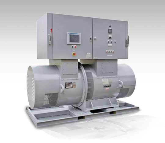
Aviation Ground Power Kato Motor-Generators
Our customers rely on the reliability, durability and quality of the Kato Engineering 400Hz Motor-Generator set design. Backed by over 85 years of experience, Kato MG sets were the first rotating product Kato Engineering manufactured back in 1926 and have evolved over the years to meet our customer’s special requirements and power demands of the aviation industry.
Kato Engineering’s 400Hz MG sets supply conditioned and converted generator power. Inputs are available for both 50Hz and 60Hz. Power capacities range from 25 kVA to 400 kVA. When utilizing multiple paralleled MG sets, the power capacities are limitless.
400Hz MG customers include; commercial applications (airports and aircraft manufacturing), military (flight decks, global Air Force bases, tethered missile detection), as well specialty applications including radar and 400Hz testing
Advantages & Features
- Made in the U.S.A.
- Proven technology backed by 85 years of experience.
- Long standing life cycles in excess of 100,000 hours.
- Low maintenance cost.
- 12” Touch Screen, Human Machine Interface (HMI).
- Ethernet/IP communications standard.
- Low harmonics.
- Protective relays.
- Transient spike protection.
- High overload capacity.
STANDARD MODELS
| Voltage | kW | kVA |
| 200-208 | 75 | 93.75 |
| 200-208 | 144 | 180 |
| 575 | 144 | 180 |
| 575 | 250 | 312 |
| 575 | 320 | 400 |
| 575 | 400 | 400 |
MG SET
Speed: 1200 RPM
Efficiency: See table below
Duty Cycle: Continuous
Overload: 110%, 2/24 hours
Temperature: 95°C rise/ 40°C ambient
Insulation: Class H
Excitation: Brushless synchronous
Construction: Open dripproof enclosure for rotating part. Common frame single-shaft two-bearing horizontal construction for low vibration and ease of maintenance. Stator built with silicon electrical steel laminations. Coils are film-insulated copper wire vacuum-pressure impregnated with a Class H insulation system. Rotor is laminated steel with field winding of insulated copper wire, impregnated with 100% solids resin. Bearings are re-greasable antifriction with grease fittings accessible while running.
MOTOR COMPONENT
Type: Synchronous
Poles: 6
Frequency: 60Hz
Phase: 3
Connection: Wye
Voltage: 480V
Power Factor: 1.0 nominal
NEMA Code: “A” in S-P start
Inrush Amps: See table below
Starts/hour: 2 (1 cold/1 hot per NEMA MG-1 21.13.1)
Transient: Per table below
GENERATOR COMPONENT
Type: Synchronous
Poles: 40
Frequency: 400Hz
Phase: 3
Connection: Wye
kVA and kW: See table below
Voltage: See table below
Power Factor: 0.8
Voltage Balance: 1% with balanced load (MIL-STD-704F), 4% with 33% unbalanced current
Waveform: 3% max. T.H.D., 2% max. individual harmonic w.r.t. fundamental, linear load
Transient: See table below
CONTROLS COMPONENT
Enclosure: NEMA 1 steel mounted on top of the M-G set. Cable entry through top.
| Generator | ||||||
| Voltage | 200-208 | 200-208 | 575 | 575 | 575 | 575 |
| Rated kW | 75 | 144 | 144 | 250 | 320 | 400 |
| Rated kVA | 93.75 | 180 | 180 | 312 | 400 | 400 |
| Transient | ||||||
| 0-50% load | -9.0% | -8.0% | -8.0% | -7.0% | -12.5% | -8.3% |
| Sec to 95% | 0.150 | 0.150 | 0.050 | 0.260 | 0.260 | 0.150 |
| 0-100% load | -18.0% | -16.0% | -16.0% | -14.0% | -22.5% | -15% |
| Sec to 95% | 0.150 | 0.150 | 0.150 | 0.320 | 0.320 | 0.150 |
| 50-0% load | 11.0% | 10.0% | 10.0% | 8.0% | 13.5% | 9% |
| Sec to 105% | 0.160 | 0.160 | 0.160 | 0.260 | 0.260 | 0.160 |
| 100-0% load | 22% | 20% | 20% | 16% | 28% | 20% |
| Sec to 105% | 0.160 | 0.160 | 0.160 | 0.320 | 0.320 | 0.160 |
| Motor | ||||||
| HP at Gen FL | 125 | 210 | 210 | 360 | 470 | 560 |
| Amps at FL | 116 | 205 | 205 | 355 | 445 | 550 |
| A-Series start | 185 | 390 | 390 | 750 | 850 | 900 |
| SkVA/Hp (ser) | 1.3 | 1.5 | 1.5 | 1.6 | 1.5 | 1.3 |
| Code letter | A | A | A | A | A | A |
| MG Set | ||||||
| Efficiency at P.F. | ||||||
| @ 2/4 Load | 80.6% | 82.3% | 82.3% | 82.0% | 84.0% | 85.2% |
| @ 4/4 Load | 81.2% | 84.5% | 84.5% | 86.0% | 87.0% | 89.0% |
| Paralleling | No | No | No | Yes | Yes | Yes |


